Q
IGMP Filtering
A
Question:
I have one question about the IGMP Filtering permit behavior.
- I can understand the “deny” behavior is “NOT to allow the port to receive the specific multicast address.
- But what is the “permit” behavior? Can the port only receive the specific multicast address?
- When the IGMP filtering enable, does it mean all ports follow the filtering table? What is the port IGMP Snooping behavior if it is not bind to the profile?
Answer:
For IGMP filtering, you can config Maximum 10 profiles, each Profile you can config Maximum 10 multicast groups
The type rule
“Deny” means drop
“Permit” means allow
When you filter on specific port, it will check the Filtering table and only allow multicast in range “Permit”. Thus, you should filter for downlink ports only
When IGMP filtering enabled, it will activate the global config on SW
Once you add specific profile to interface, the filtering process will start
And from now on, IGMP Snooping will depend on IGMP filtering rule for multicast traffic allow or drop
Q
Where can I configure VLAN priority?
A
For VLAN priority, you can configure by
- Port-based
- QinQ
- MAC-Based
- ALC
Q
IGMP snooping filtering
A
Role 1: Bind Deny profile(The port only deny the specific multicast address traffic, others can receive)
Role 2: Bind Permit profile (The port only permit to receive the specific multicast address traffic, others cannot receive)
Role 3: No bind any profile (The port is like a general port to receive the all multicast address traffic when client send out the associated the IGMP report packets).
Answer: You can bind deny and permit profile at a time for any specific port
And the example rule to drop or allow any multicast IP as below
Eg: You create 2 profile and bind under port 1
- Profile 1 with group 227.1.1.1 ~ 227.1.1.100 => Type “Deny”
- Profile 2 with group 227.1.1.200 ~ 227.1.1.250 =>type “Permit”
The SW will check Profile 1 first then turn to Profile 2
So results on port 1 as below
+ Multicast IP: 227.1.1.1~227.1.1.100 => drop
+ Multicast IP: 227.1.1.200~227.1.1.250 => pass
+ Other Multicast IP pass under profile 1, but drop under profile 2
If you have command initially add profile 2 to port 1 then Profile 1, the SW will check the rule on Profile 2 first then turn to profile 1
So results on port 1 as below
n Multicast IP: 227.1.1.200~227.1.1.250 => pass, as it initially check profile 2
n Other Multicast IP => drop, in this case profile 1 has no meaning
Q
In IGMP Filtering, the “deny” behavior is “NOT to allow the port to receive the specific multicast address." But what is the “permit” behavior? Can the port only receive the specific multi-cast address? Also, when the IGMP filtering is enabled, does it me
A
For IGMP Filtering, you can config Maximum 10 Profiles, each Profile you can config Maximum 10 multicast groups.
- "Deny” means drop
- "Permit” means allow
When filtering on a specific port, it will check the Filtering Table and only allow multi-cast in its range to “Permit”. Thus, you should filter for downlink ports only.
When IGMP filtering isenabled, it will activate the global config on the switch. Once you add a specific profile to the interface, the filtering process will start. At that point, IGMP Snooping will depend on the IGMP Filtering rules for multi-cast traffic allow or drop.
Q
Explain IGMP Snooping Filtering
A
Role 1: Bind Deny Profile (The port only denies the specific multi-cast address traffic, it can receive other traffic)
Role 2: Bind Permit Profile (The port is only permitted to receive the specific multi-cast address traffic, it cannot recieve other traffic)
Role 3: No Bind Any Profile (The port is a general port to receive the all multi-cast address traffic when the client sends out the associated IGMP report packets).
Answer: You can bind deny and permit profile at a time for any specific port
The example below shows the rules to drop or allow any multi-cast IP
Eg: You create 2 profiles and bind under port 1
- Profile 1 with group 227.1.1.1 ~ 227.1.1.100 => Type “Deny”
- Profile 2 with group 227.1.1.200 ~ 227.1.1.250 =>type “Permit”
The switch will check Profile 1 first then turn to Profile 2
The results on port 1 are shown below
+ Multicast IP: 227.1.1.1~227.1.1.100 => drop
+ Multicast IP: 227.1.1.200~227.1.1.250 => pass
+ Other Multicast IP pass under profile 1, but drop under profile 2
If you initially commanded to add profile 2 to port 1 then Profile 1, the switch will check the rule on Profile 2 first, then turn to Profile 1.
The results on port 1 are shown below
Multicast IP: 227.1.1.200~227.1.1.250 => pass, as it initially check profile 2
Other Multicast IP => drop, in this case profile 1 has no meaning
Q
What is default username and password to login to a switch?
A
Username: admin
Password: admin
Q
What are the CLI modes while configuring in Volktek Managed Switches?
A
| CLI Modes in Volktek Switches | Symbol/Command |
| User Mode | > |
| Privilege Mode | # |
| Global Configuration Mode | (config)# |
| Interface Configuration Mode | (config-if)# |
Q
What methods can I access a switch?
A
1. Managed Switches
- GUI
- Console and
- Telnet
2. Lite-Managed Switches
GUI
3. Un-managed switches
No
Q
What is the default IP address of Volktek switches?
A
192.168.0.254
Q
How can I configure the parameters for 802.1x on Volktek switches?
A
1. In global configuration:
- Choose state enable/disable to activate this function
- Choose which method you prefer: Local or Radius
- Guest VLAN: Keep as default “0”, if you configure it, please configure on access ports, not on trunk ports
- Input Primary/Secondary server info
- Input Local Users/Passwords
2. In port setting
- You must enable state, and don’t enable all ports at the same time
- Control direction: In your preference
- Reauthentication
#Disable: If you don’t need supplicant to re-enter username/password when re-auth
#Enable: If you want supplicant to enter username/password when re-auth
>> For convenience: You should disable (Which means the switch Authenticator will do itself)
- Port Control: Keep as Auto
- Guest VLAN: Depends on your global config
- Max-req timer: Base on your preference
- Reauth-period or reAuthWhen: A timer used by the Reauthentication Timer state machine to determine when reauthentication of the Supplicant takes place.
- Quiet Period or QuietWhile: A timer used by the Authenticator (SW) state machine to define periods of time during which it will not attempt to acquire a Supplicant.
- Supp-timeout or authWhile: A timer used by the Supplicant to determine how long to wait for a request from the Authenticator before timing it out.
- Server-timeout or aWhile: A timer used by the Backend Authentication state machine in order to determine timeout conditions in the exchanges between the Authenticator and EAP.
We have no recommendation for you, but hope the above information will help you decide the parameters.
Q
What do T and A stand for in LACP status?
A
Both T & A indicate member ports in LACP, where T is an inactive link (link down) and A is an active link (link up).
Q
What is the maximum number of units for Storm Control on INS-8648P?
A
Each unit = 652pps. Max units which can be configured = 1488000/652 = 2282 ~ 2300 units.
Q
The Management Host is in VLAN 30; how should this be configured to manage INS-8648P?
A
If user configures the Management Host, the switch can only be managed by the host. The Max Host that can be configured is 3, and the Host IP should be under the same management VLAN.
Q
About the power alarm on INS-8648, the power input range is 12 to 60 VDC. Is there any reason to set > 57V DC to trigger an alarm?
A
The power circuit for this model ranges from 12 to 57VDC. The switch can accept an input voltage up to 60V, though it will generate an alarm when power is over 57VDC.
Q
Can Dual Homing work with link aggregation?
A
Yes. Dual Homing can work with LACP. Under the Dual Homing setting, you can configure active/backup link by port or trunk.
Q
Is there a log when the port is disabled by the loop detection algorithm?
A
Yes, the switch will generate a log.
Q
What is Loop Detection?
A
The Loop Detection feature in Volktek switches detects a loop in the network, blocks the port causing the loop and avoids degradation of network performance.
Q
What precautions should be taken to avoid over heating of the switch?
A
1. Install a larger network cabinet for proper airflow and heat dissipation.
2. Avoid installing cables in front of switch and network cabinet air vents.
3. In case of a fully-enclosed cabinet, use exhaust fans and perforated walls or doors to facilitate air flow
Q
How to enable/disable Web GUI in Volktek switches?
A
(Web GUI is enabled by default setting)
- To Enable Web GUI through CLI:
L2SWITCH(config)#http server port 80
- Disable Web GUI through CLI:
L2SWITCH(config)#no web server
- Disable Web GUI through GUI:
Go to Maintenance >> choose Server and Disable
Q
How can I implement PoE Scheduling?
A
Example:
| Week | Check | Action | Start | End |
| Monday | Yes | Enable | 0 | 7 |
| Monday | Yes | Enable | 19 | 24 |
Instead of taking Action "enable" for your required time range, you can take Action “disable” for the time 7~19
Monday
Week
Check
Action
1
2
3
4
5
6
7
8
»
Q
When the switch cycles power, which PoE ports are powered first?
A
Example:
The total PoE power is 90W. Each port's powered devices requires 30W.
| Port | PoE Priority | Power Delay (seconds) |
| 1 | Critical | 50 |
| 2 | Critical | 51 |
| 3 | Critical | 52 |
| 5 | Low | 10 |
Once power cycles, the switch will provide power base on a power delay. Thus, the PD under port 4, 1, 2 will have power and port 3 has no power. Once port 4 link is down/up, then port 3 will have power. It is better to configure high priority ports with low value for power delay.
Q
If the switch has power cycled, what is the sequence to provide power? By port sequence?
A
If power is cycled, all PoE ports will turn on at the same time. If this potentially causes an issue, the used can configure a power delay for each port and determine which ports will have PoE first.
Q
If a new "PD" plugs into a "high" priority port, will the switch ignore the power requested? Or will the switch drop to the lower priority port?
A
The switch will not drop to a lower priority port at that time, it will take effect when the link is down or power is cycled.
Q
There is a PoE function called "Start-up Time" which means the switch will conduct the auto-checking the powered device (PD) after this time. How does the switch know the PD system is ready?
A
Start-up Time is the time the switch will ping to the PD initially after the PD has been start-up. If the PD responds, the switch will use the Interval + Retry setting to continue the next communication. If the PD has no response, then the switch will take Action setting. The Start-up time setting can be configured from 60~300 seconds which the user can configure base on the specific PD re-booting time.
Q
I found the setting in static multicast address setting is used “MAC address” not “IP group address. May I know the reason?
A
For IGMP snooping and MVR, user can set the multicast IP address, then SW will translate to MAC address. For static multicast MAC address, this is L2 function and use in special case when user understand and want to fix this MAC to specific ports.
Q
What is the default IP address of Volktek switches?
A
192.168.0.254
Q
Where can I configure VLAN priority?
A
For VLAN priority, you can configure by
- Port-based
- QinQ
- MAC-Based
- ALC
Q
What precautions should be taken to avoid over heating of the switch?
A
1. Install a larger network cabinet for proper airflow and heat dissipation.
2. Avoid installing cables in front of switch and network cabinet air vents.
3. In case of a fully-enclosed cabinet, use exhaust fans and perforated walls or doors to facilitate air flow
Q
What is default username and password to login to a switch?
A
Username: admin
Password: admin
Q
What are the CLI modes while configuring in Volktek Managed Switches?
A
| CLI Modes in Volktek Switches | Symbol/Command |
| User Mode | > |
| Privilege Mode | # |
| Global Configuration Mode | (config)# |
| Interface Configuration Mode | (config-if)# |
Q
What methods can I access a switch?
A
1. Managed Switches
- GUI
- Console and
- Telnet
2. Lite-Managed Switches
GUI
3. Un-managed switches
No
Q
When does a Switching Loop occur in a network?
A
A Switching Loop occurs in a network when there are more than one Layer 2 (OSI model) paths between two endpoints. For example, multiple connections between two network switches or two ports on the same switch connected to each other will create a loop and result in a down network situation.
Q
Why do I lose switch connection after I upgrade to Device-Lock firmware?
A
It is necessary to have consistent links and authentications between SLAVE and MASTER in different deployment scenarios. Please contact our technical support team if you encounter such problem at support@volktek.com.
Q
What are the roles and benefits of the Device-Lock feature?
A
Roles of the Device-Lock feature:
- Master: Master is the authenticator which processes authentication request from SLAVE devices so that all ports are ready for port forwarding.
- Master-Slave: This is a hybrid role. It sends authentication requests to the master device through uplink ports. Once it is authenticated, it will open downlink ports for the SLAVE device to become authenticated.
- Slave: Slave is supplicant which gets authenticated together with the master device through specified uplink ports. Before a successful authentication, all downlinks are blocked, and no services are possible.
Benefits:
- Lock the switch to a specific network
- Switch will not function in any networks other than its configured network
- Reduces device thefts at the last mile
Q
What is Device Lock feature?
A
Device Lock is a customized feature designed to lock the switch to a particular network. By enabling the device lock feature, the switch is locked to function only on the configured network. This feature significantly reduces device thefts at the last-mile.
Q
Once the Device Lock feature is enabled, can I downgrade the firmware to older versions?
A
No.
Q
How do I restore the switch to Non-Device-Locking mode?
A
Contact Volktek at support@volktek.com with the following details:
- Contact Person
- Company Name
- Switch Model
- MAC
- Serial No.
- Distributor
Q
Can a Device Lock role be exchanged with other roles?
A
No.
Q
Once the Device Lock feature is enabled, can I disable it?
A
No.
Q
If the Device Lock feature is enabled, how many times can I change the default vendor key?
A
One time.
Q
What are the roles of the Device Lock feature?
A
Master, Slave, and Master-slave.
Q
How to ensure that my Volktek switches are not accessible to anyone if stolen?
A
Enable the Device Lock feature to restrict unauthorized authentication.
Q
What is the purpose of the Device Lock feature?
A
Device Lock is a customized feature designed to lock the switch to a particular network. By enabling the Device Lock feature, the switch will function only in the configured domain and will not function in any other network, thereby reducing device thefts at the last mile.
Q
Do Access Switches support L3 functions?
A
Access Switches do not support L3 functions as they are L2+ switches
Q
What is the power consumption of MEN-4210?
A
14W
Q
Can I downgrade the firmware after upgrading it to a Device-Lock version?
A
Users can downgrade or upgrade to Device-Lock firmware. However, for security reasons, we don’t allow users to downgrade from Device-Lock firmware to a normal version. If you require a downgrade, please contact our technical support team at support@volktek.com.
Q
SFP details are not reflected in port 9 (MEN-3410)
A
This is a firmware related issue. Please contact our Technical Support at support@volktek.com for the latest firmware.
Q
Do Access Switches support MSTP?
A
Access Switches only support STP/RSTP
Q
What is the charging current for MEN-4210?
A
| Model Charging | Current |
| MEN-4210 | 0.8Amps |
Q
Why doesn"t Loop Detection block the port immediately when a loop is detected?
A
This is a firmware related issue. Please contact our Technical Support at support@volktek.com for the latest firmware.
Q
What are the commands to change management IP on MEN-3410/MEN-4210?
A
Commands to change management IP:
- MEN-3410(config)#interface eth0
- MEN-3410(config-if)#ip address ABCD/M
- MEN-3410(config-if)#ip address default-gateway ABCD
To enable DHCP client:
- MEN-3410(config)#interface eth0
- MEN-3410(config-if)#ip dhcp client enable
Change management IP through GUI:
Under "General Setting", you can change hostname, DHCP client enable/disable, configure static IP address, subnet mask, default gateway, and management VLAN.
Q
How to configure management VLAN on MEN-3410/MEN-4210?
A
Commands to configure management VLAN
- MEN-3410(config)#interface eth0
- MEN-3410(config-if)#management vlan
Configure management VLAN through Web GUI
Under "General setting", you can change hostname, DHCP client enable/disable, configure static IP address, subnet mask, default gateway, and management VLAN.
Q
How to configure port isolation on MEN-3410?
A
Commands to configure port isolation:
- MEN-3410(config)#interface fa1/0/1
- MEN-3410(config-if)#port-isolation ports 1,9-10,0
- 1 → Interface Id
- 9-10 → Uplink ports
- 0 → CPU
Through Web GUI:
Under VLAN menu, select port isolation. Downlink ports should be isolated.
Select port ID & Egress Port (uplink ports) and click on 'Apply' to configure port isolation.
Port status ‘V’ indicates that port packet can be sent to that port.
Port status ‘-’ indicates that port packet cannot be sent to that port.
Q
Email alarm features do not work with other email domains (Gmail server)
A
Security settings of public domain mail servers such as gmail or yahoo may cause this issue. You need to enable those mail servers to allow less secured apps to work. Email alarm features work best with private domains.
Q
Switch restarts when the "reset" button is used
A
The reset button on the switch is designed to restart the switch. When it is pressed for over 5 seconds, the switch will load to factory default settings.
Q
SFP details do not reflect in port 9.
A
This is a firmware related issue. Please contact our Technical Support at support@volktek.com for the latest firmware.
Q
The DHCP Snooping feature not working
A
This is a firmware related issue. Please contact our Technical Support at support@volktek.com for the latest firmware.
Q
Ports randomly hang
A
This is a firmware related issue. Please contact our Technical Support at support@volktek.com for the latest firmware.
Q
How to enable/disable Web GUI in Volktek switches?
A
(Web GUI is enabled by default setting)
- To Enable Web GUI through CLI:
L2SWITCH(config)#http server port 80
- Disable Web GUI through CLI:
L2SWITCH(config)#no web server
- Disable Web GUI through GUI:
Go to Maintenance >> choose Server and Disable
Q
I found the setting in static multicast address setting is used “MAC address” not “IP group address. May I know the reason?
A
For IGMP snooping and MVR, user can set the multicast IP address, then SW will translate to MAC address. For static multicast MAC address, this is L2 function and use in special case when user understand and want to fix this MAC to specific ports.
Q
IGMP snooping filtering
A
Role 1: Bind Deny profile(The port only deny the specific multicast address traffic, others can receive)
Role 2: Bind Permit profile (The port only permit to receive the specific multicast address traffic, others cannot receive)
Role 3: No bind any profile (The port is like a general port to receive the all multicast address traffic when client send out the associated the IGMP report packets).
Answer: You can bind deny and permit profile at a time for any specific port
And the example rule to drop or allow any multicast IP as below
Eg: You create 2 profile and bind under port 1
- Profile 1 with group 227.1.1.1 ~ 227.1.1.100 => Type “Deny”
- Profile 2 with group 227.1.1.200 ~ 227.1.1.250 =>type “Permit”
The SW will check Profile 1 first then turn to Profile 2
So results on port 1 as below
+ Multicast IP: 227.1.1.1~227.1.1.100 => drop
+ Multicast IP: 227.1.1.200~227.1.1.250 => pass
+ Other Multicast IP pass under profile 1, but drop under profile 2
If you have command initially add profile 2 to port 1 then Profile 1, the SW will check the rule on Profile 2 first then turn to profile 1
So results on port 1 as below
n Multicast IP: 227.1.1.200~227.1.1.250 => pass, as it initially check profile 2
n Other Multicast IP => drop, in this case profile 1 has no meaning
Q
Where can I configure VLAN priority?
A
For VLAN priority, you can configure by
Q
What is the default IP address of Volktek switches?
A
192.168.0.254
Q
Explain IGMP Snooping Filtering
A
Role 1: Bind Deny Profile (The port only denies the specific multi-cast address traffic, it can receive other traffic)
Role 2: Bind Permit Profile (The port is only permitted to receive the specific multi-cast address traffic, it cannot recieve other traffic)
Role 3: No Bind Any Profile (The port is a general port to receive the all multi-cast address traffic when the client sends out the associated IGMP report packets).
Answer: You can bind deny and permit profile at a time for any specific port
The example below shows the rules to drop or allow any multi-cast IP
Eg: You create 2 profiles and bind under port 1
- Profile 1 with group 227.1.1.1 ~ 227.1.1.100 => Type “Deny”
- Profile 2 with group 227.1.1.200 ~ 227.1.1.250 =>type “Permit”
The switch will check Profile 1 first then turn to Profile 2
The results on port 1 are shown below
+ Multicast IP: 227.1.1.1~227.1.1.100 => drop
+ Multicast IP: 227.1.1.200~227.1.1.250 => pass
+ Other Multicast IP pass under profile 1, but drop under profile 2
If you initially commanded to add profile 2 to port 1 then Profile 1, the switch will check the rule on Profile 2 first, then turn to Profile 1.
The results on port 1 are shown below
Multicast IP: 227.1.1.200~227.1.1.250 => pass, as it initially check profile 2
Other Multicast IP => drop, in this case profile 1 has no meaning
Q
What methods can I access a switch?
A
1. Managed Switches
- GUI
- Console and
- Telnet
2. Lite-Managed Switches
- GUI
3. Un-managed switches
- No
Q
What are the CLI modes while configuring in Volktek Managed Switches?
A
| CLI Modes in Volktek Switches | Symbol/Command |
| User Mode | > |
| Privilege Mode | # |
| Global Configuration Mode | (config)# |
| Interface Configuration Mode | (config-if)# |
Q
What is default username and password to login to a switch?
A
Username: admin
Password: admin
Q
What is Loop Detection?
A
The Loop Detection feature in Volktek switches detects a loop in the network, blocks the port causing the loop and avoids degradation of network performance.
Q
When does a Switching Loop occur in a network?
A
A Switching Loop occurs in a network when there are more than one Layer 2 (OSI model) paths between two endpoints. For example, multiple connections between two network switches or two ports on the same switch connected to each other will create a loop and result in a down network situation.
Q
What precautions should be taken to avoid over heating of the switch?
A
1. Install a larger network cabinet for proper airflow and heat dissipation.
2. Avoid installing cables in front of switch and network cabinet air vents.
3. In case of a fully-enclosed cabinet, use exhaust fans and perforated walls or doors to facilitate air flow.
Q
Which ports are recommended for enabling the Loop Detection feature?
A
Downlink ports.
Q
What will be the port status and LED status when the Loop Detection feature is enabled and a loop is detected?
A
Port status – Blocked
LED status – Off
Q
Why does the Volktek switch lose connectivity with the Monitoring tool?
A
This issue is related to Monitoring tool (3rd party application)
Q
When should I enable the Traffic Monitoring feature on the Volktek switch?
A
When your switch ports are flooding with broadcast, multi-cast, and unknown uni-cast (also referred to as Destination Look-up Failure or DLF) packets and you want to block the ports.
Q
Can both Storm Control and Traffic Monitoring features be enabled at the same time on Volktek switch?
A
No. Only one feature can be enabled at a time.
Q
The port is not blocked after enabling the Storm Control feature on the Volktek switch. What can be the reason?
A
Storm Control feature only limits or restricts the packets flooding the port as configured. To block the port, enable the Traffic Monitoring feature.
Q
What is management VLAN? What are the benefits of network management?
A
A management VLAN is used to establish an IP connection to the switch from a workstation connected to a port in the VLAN and manage the switch from a remote location using protocols such as Telnet, SSH, SNMP, etc. By default, the active management VLAN is VLAN1, but you can designate any VLAN as management VLAN. Only one management VLAN can be active at a time.
Benefits
Q
Best Practices for Installation
A
These general installation and maintenance instructions are provided by the Volktek support team. Always follow standard recommendations relating to proper installation, testing, maintenance, and reconditioning. In order to maximize system capabilities and avoid potential pitfalls, installers need to have an understanding of the best practices in configuring Ethernet network infrastructure for the factory floors.
I. Do Proper Earthing:
The Switches, Network Cabinet, and Rack to be placed in buildings or installation sites are kept above certain height from the ground level.
1. Why we need to do proper Earthing?
✓ To prevent exposing the switch to ESD
✓ To prevent the causes of equipment failure
2. How to check the Earthing Condition?
✓ Use a multi-meter and connect Red probe in Earth and Black probe in Neutral
✓ Ideal Voltage reading should be less than 3V
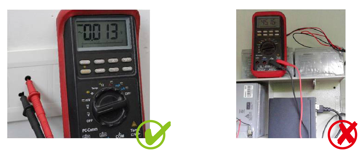
II. Choose the proper size of cabinet/enclosure with door
Improper airflow due to limited space in the network cabinet leads to switch overheating, especially for industrial applications.
Benefits of a Bigger Cabinet
✓ Ample air space
✓ Good airflow
✓ Quicker heat dissipation
✓ Better switch performance
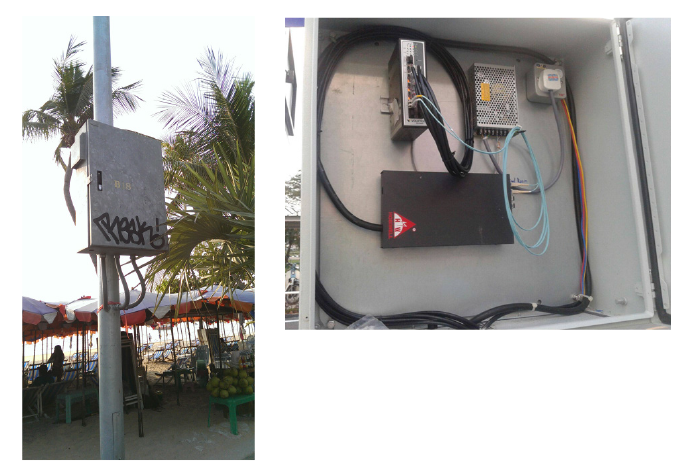
III. Correct DIN-Rail Installation and Power Inserting
1. Installation Flow Chart
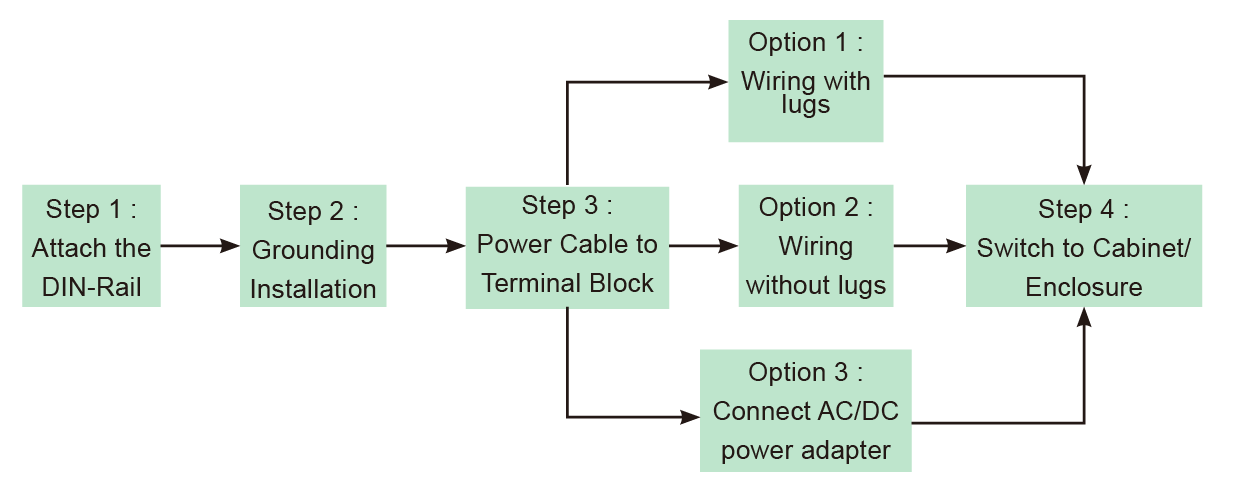
2. Step 1: Attach the DIN-Rail to the back of the cabinet/enclosure
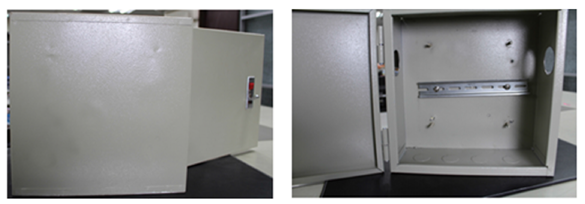
3. Step 2: Grounding Installation
✓ Use a screwdriver to loosen the grounding on the switch
✓ Attached the grounding lug to the M4 screw grounding receiver
✓ Tighten the screws to prevent the lug from loosening
✓ Place the switch on the DIN-Rail then push the front of the switch toward the mounting surface until it snaps into place with a click sound
✓ Connect grounding wire to the grounding screw on cabinet/enclosure
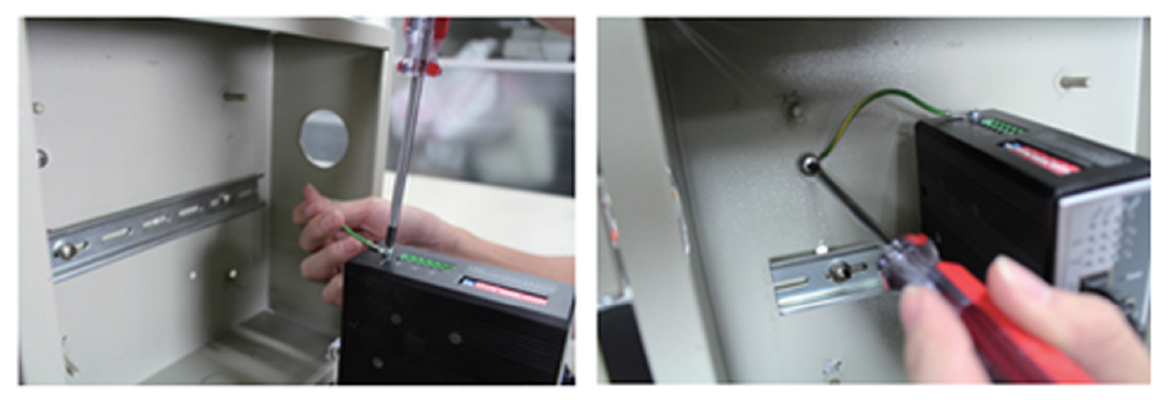
4. Step 3: Wiring the cable and power on the switches
a. Wiring the cable
✓ Use a flat-head screwdriver to loosen the wire-clamp screws
✓ Insert the corresponding positive/negative into the contact receivers on the terminal block.
✓ Tighten the wire-clamp screws to prevent the lugs from loosening
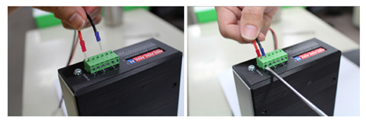
b. Power inserting and power on the switches
✓ Using voltage measure to make sure the input voltage is within the range of proper power input specification.
✓ Assemble the positive and negative electric wire to the terminal block correctly as in “Wiring the cable”
✓ Using voltage measure to make sure the input voltage is in the operation range
✓ Turn off power source
✓ Plug the terminal block into the switch completely.
✓ Then turn on the power source
✓ After self-diagnosis, check the LED status on the switch to make sure it already successfully operated.
IV. Use two available power source to prevent network interruptio
Q
Giving Proper Maintenance
A
1. Prevent against network storms
Correct configuration of the network, using a robust ring resiliency protocol between the switches is necessary for network redundancy as well as loop prevention. One can prefer ERPS or Xpress rings for industrial use as their network recovery rate is below 50msec.
2. Proper configuration for high-Security authentication on all connected ports
Switch ports should be set up to never allow data exchange with a connected device until that device has provided authentication credentials that have been verified by the network’s authentication server. The switch ports which are not used should be disabled/shut down to prevent being hijacked in any way.
3. Real-time network Alarm
Volktek provides various options for real-time network alarm from hardware to software. With 24V/1A terminal connection through hardware to allow connects to the alarm system. Standard network management protocols, Syslog, Email Alarm provide messages that are sent upon state change like ports being plugged or unplugged, un-authentication access etc. Network Management Stations receive and display these alarms so that necessary action can be taken on the network connected devices.
Q
How did our switch behave in case of cable damage and short circuit on an active PoE port? if some wires will then have a short circuit (during operation)? What will happen in the switch? Is there some kind of protection without any damage?
A
1. Our PoE switch (PSE chip) had 2 kinds over load protection
Surge current protection: over current af: 892mA at:1200mA)
PSE chip also can offer over 15.5W/30W in af/at mode(max af: 448mA, at: 767mA), when over max current also cute off power.
2. UL must test POE system in shorted that system must enable protected function. Chip vender had approved by UL.
3. Volktek design fuse for double protecting in over load or shorted to protection PSE chips in all PoE switch.
4. If over current over fuse spec, fuse will be destroyed.
Q
IGMP Filtering
A
Question:
I have one question about the IGMP Filtering permit behavior.
I can understand the “deny” behavior is “NOT to allow the port to receive the specific multicast address.
But what is the “permit” behavior? Can the port only receive the specific multicast address?
When the IGMP filtering enable, does it mean all ports follow the filtering table? What is the port IGMP Snooping behavior if it is not bind to the profile?
Answer:
For IGMP filtering, you can config Maximum 10 profiles, each Profile you can config Maximum 10 multicast groups
The type rule
“Deny” means drop
“Permit” means allow
When you filter on specific port, it will check the Filtering table and only allow multicast in range “Permit”. Thus, you should filter for downlink ports only
When IGMP filtering enabled, it will activate the global config on SW
Once you add specific profile to interface, the filtering process will start
And from now on, IGMP Snooping will depend on IGMP filtering rule for multicast traffic allow or drop.
Q
When does a Switching Loop occur in a network?
A
A Switching Loop occurs in a network when there are more than one Layer 2 (OSI model) paths between two endpoints. For example, multiple connections between two network switches or two ports on the same switch connected to each other will create a loop and result in a down network situation.
Q
What is maximum distance does copper SFP 10/100/1000 support?
A
Copper SFP 10/100/1000 supports a maximum distance of 100 meters.
Q
The port is not blocked after enabling the Storm Control feature on the Volktek switch. What can be the reason?
A
The Storm Control feature only limits or restricts the packets flooding the port as configured. To block the port, enable the Traffic Monitoring feature.
Q
When should I enable the Traffic Monitoring feature on the Volktek switch?
A
The traffic monitoring function is enabled when your switch ports are flooding with broadcast, multicast, and unknown unicast (also referred to as Destination Look-up Failure or DLF) packets and want to block the ports. Third-party monitoring tools may be considered as threats and present connection loss or integration issues.
Q
What is Loop Detection?
A
The Loop Detection feature in Volktek switches detects a loop in the network, blocks the port causing the loop and avoids degradation of network performance.
Q
Why does the Volktek switch lose connectivity with a third party monitoring tool?
A
There might be a connection loss or integration issue with the third-party monitoring tool. Try disabling the Traffic Monitoring tool to discard this could be the reason and test it one more time.
Q
Can both Storm Control and Traffic Monitoring features be enabled at the same time on Volktek switches?
A
No. Only one feature can be enabled at a time.
Q
What type of protections does a Volktek switch offer if there is a cable damage or a short circuit on an active PoE port?
A
a) Volktek PoE switches have 2 kinds of overload protection Surge current protection: Over current IEEE 802.3 af: 892mA and IEEE 802.3 at:1200mA, while PSE chips also can offer over 15.4W/30W in IEEE 802.3 af/at mode (max IEEE 802.3 af: 448mA, IEEE 802.3 at: 767mA) When the power current exceeds the max the switch cuts the power automatically.
b) Is mandatory for PoE chip vendors to have UL approval. PoE systems have to be tested under short circuit conditions that enable the protection function to confirm it is safe of use. Volktek PoE switches are designed with a fuse that conducts electricity during overload and shorted situations to protect PSE chips. The fuse will be destroyed and the device is safe from damage. If over current over fuse spec, the fuse will be destroyed and save the device from damage.
Q
I found the setting in static multicast address setting is used “MAC address” not “IP group address. May I know the reason?
A
For IGMP snooping and MVR, user can set the multicast IP address, then SW will translate to MAC address. For static multicast MAC address, this is L2 function and use in special case when user understand and want to fix this MAC to specific ports.
Q
How to enable/disable Web GUI in Volktek switches?
A
(Web GUI is enabled by default setting)
- To Enable Web GUI through CLI:
L2SWITCH(config)#http server port 80
- Disable Web GUI through CLI:
L2SWITCH(config)#no web server
- Disable Web GUI through GUI:
Go to Maintenance >> choose Server and Disable
Q
The INS-8528 switch connects a ring through 4 media converters (MC). When one fiber is broken, does the fast ring still work? Or can only a broken copper wire can trigger the fast ring to work?
A
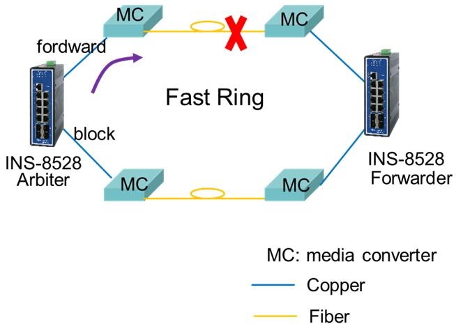
The MC doesn't support LFP (Link Fail Pass-through). The Xpress Ring works when it receives a link down notification from the forwarding port to change the state of the blocking port. This means that it will work under the following conditions:
- The connection from Arbiter to MC is linked down (forward copper port link down).
- If the fiber port link is down, then MC must support LFS that must be enabled.